TinyGS is an open network of Ground Stations distributed around the world to receive and operate LoRa satellites, weather probes and other flying objects, using cheap and versatile modules. Here we will be discussion about tracking and receiving data packets from LoRa supported satellites.

This project is based on ESP32 boards and currently it is compatible with sx126x and sx127x LoRa modules but we plan to support more radio modules in the future.
Initially TinyGS was born under the name ESP32 Fossa Groundstation, it was developed as a "weekend" project for the FossaSAT-1 LoRa satellite.
Currently the network is open to any LoRa satellite and we also support other flying objects that have a compatible radio modulation with our hardware such as FSK, GFSK, MSK, GMSK, LoRa and OOK. And the project was renamed to TinyGS.
What is LoRa ? Defnition as per Wiki..
LoRa (Long Range) is a proprietary low-power wide-area network modulation technique. It is based on spread spectrum modulation techniques derived from chirp spread spectrum (CSS) technology. It was developed by Cycleo of Grenoble, France and acquired by Semtech, the founding member of the LoRa Alliance and it is patented.
LoRa uses license-free sub-gigahertz radio frequency bands like 433 MHz, 868 MHz (Europe), 915 MHz (Australia and North America), 865 MHz to 867 MHz (India) and 923 MHz (Asia). LoRa enables long-range transmissions with low power consumption.
TinyGS network architecture

Setting up a Tiny Ground Station
Following are the essential things required to setup as TinyGS station. The details provided below are specific to my build and can easily be modified based hardware supply and availability in your locality. Here is the well documented git page of the TinyGS project.1. ESP 32 Development Board (Checkout the list of supported hardware from here)

2. LoRa RA-02 Module (I have used a AiThinker 433MHz type)

4. Few Jumper wires
5. 5V DC power Supply Adapter
6. A good tuned Antenna (Most Important)
6. A good tuned Antenna (Most Important)
Hardware Connectivity
First of all we need to build a 2.54mm pitch compatible leg adapter for LoRa RA02 module. It can be easily done by soldering the castle pins of module to a zero board. I have used single copper wire pieces from a 1mm sq. multi strand wire. Now it is easy to solder a 2.54mm pitch berg pins.

Next part is to carefully wire the LoRa Module to ESP32 board. If you are using Lilygo T3v2.1.6 board which comes with inbuilt LoRa Module it might be required to modify the Board Profile. Will be discussed in detail below.


Building and tuning the Antenna
We will be discussing about building and tuning an antenna. There are many popular antennas for satellite communication which includes QFH, Yagi, Egg-Beat, Helical antenna etc. We will be discussing about an easy to build half wave dipole antenna tuned at 440 MHz using coax cable often known as Bazooka Dipole Coax antenna. Its easy to build and tune and for fine tuning I have used Nano VNA. List of materials required for building a Bazooka Diploe.
- A piece of RG-6 Coaxial Cable
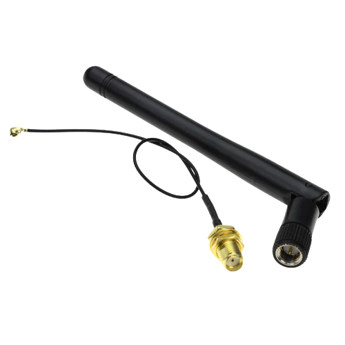
- SMA Male connector (I extracted it from the wifi dummy antenna which came along with IPEX Cable)
- A two Pin AC plug socket
- Left over parts of the wifi dummy antenna. (ref . picture below)
Here is the link for design and calculation of Bazooka Antenna of desired frequency band. Given below is the length for 448 MHz. The picture below clearly shows the soldering points. The main antenna element is made of RG-6 Cable of which the shield is cut and separated in center. Pls note that the center conductor is intact at the center. On both ends the shield is connected to the center conductor and a small piece of center conducted length L2 is extended out. The feeder cable is connected to both shield in center.

Here is how I build my coax dipole. Step wise pictures given below. A short video is also added at the end for better understanding.
 |
| The white plastic object is two pin electrical wall plug with removed plug pins. |
 |
| A disassembled wifi dummy antenna |
 |
| RG-6 Coax with shield separated in center and fixed in power plug plastic support |
 |
| Partially assembled Antenna |
 |
| Completed antenna |
 |
| Testing my Antenna |
 |
| SWR min at 440 Mhz |
Ground Station Configuration
The detailed documentation for configuring the Ground station is given in the Git Page . I will give a brief idea here on how I did it.
The first step is to flash the TinyGS firmware to ESP32 board. You can do this with the help of one click uploader available for Linux, Windows and Mac. Open the application once you download on your PC (I used a windows PC for same).
 |
| Tiny GS Uploader Executable file icon |

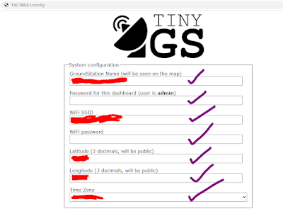
Once the upload is completed the ESP32 will reboot in Hotspot AP Mode with name "My TinyGS". Once connected to that network you can access the web panel using a web browser and going to the url 192.168.4.1.
Now fill the required details in all boxes for more details on information to be filled refer the detailed description here
When you scroll down on the browser you will be requested to fill the MQTT credentials. You can get the MQTT credentials directly from the Telegram BOT. Open the bot page and follow instructions type /mqtt and send. The BOT will reply with MQTT credentials.
 |
| Telegram Snapshot |
Also select the Board type as 433MHz TTGO LoRA32 v2 if you are using same LoRa RA-02 module as shown above. Same board need to be selected for Lilygo T3v2.1.6.


If you are using Lilygo T3v2.1.6 board as shown below. It is recommended to add board template as below to make it work with the firmware.

Board Template Text
{"name":"[433] TTGO LoRA 32 v2.1_1.6","aADDR":60,"oSDA":21,"oSCL":22,"oRST":0,"pBut":0,"led":25,"radio":1,"lNSS":18,
"lDIO0":26,"lDIO1":33,"lBUSSY":0,"lRST":23,"lMISO":19,"lMOSI":27,"lSCK":5,"lTCXOV":0.0}
Once all set click on "Apply" button. The ESP32 will reboot and the AP "My TinyGS" will vanish. If all went well your TinyGS Station will start appearing in TinyGS Home Page .
Once all set click on "Apply" button. The ESP32 will reboot and the AP "My TinyGS" will vanish. If all went well your TinyGS Station will start appearing in TinyGS Home Page .
Once your ground station is established you can get the password less link to access your ground station from the same Telegram Chat Bot. At this time open the chat bot and send /weblogin message to bot in reply BOT will share Generate and a login link for password free web access. The link will direct to the dashboard of your TinyGS and here we can modify stuffs.

Also we will get the local IP address from the dashboard using which we can login to TinyGS local console.


After configuring I have packer the entire unit inside a plastic food container as shown below and also added one DC power jack on bottom side of the container. The ground station is the tied on a metal rod and kept on my balcony as I don't have roof access . I have used a normal 5 Volt wall charger to power the unit .One twisted pair of old leftover LAN cable was used to route the power supply from wall charger to ground station unit.


Regards
No comments:
Post a Comment