So what exactly is VSWR ? .. If you are a Short wave Listener (SWL) you might have heard Ham operators discussing about there antennas and power they are pushing on Air. Some times they do mention about a term VSWR of antenna or the VSWR they read on there radio transceiver equipment.
So lets take a simple transmission system like a Radio transceiver connected to an Antenna via a RG58 (50 Ohm) coaxial cable. Consider the scenario when the Radio transmits a signal to antenna. The Signal will flow through the coaxial cable and will reach the antenna and antenna will push the signal into air. (ignoring leakage and other effects to keep the scenario simple).
Now as per above scenario we can call the Radio as a signal source and antenna as the load/Signal termination. Maximum power transfer theorem states that maximum power transfer occurs only when impedance of the source is equal to impedance of load in a transmission network. This occurs only in an ideal condition where ZS=ZL.
But what if you just connect a 50 Ohm dummy load instead to antenna ? The dummy load will satisfy the condition close to ZS~ZL and it will dissipate the power in the form of heat. The point here is that we should maintain a match in impedance between Source and Load as close as possible. It’s important to keep in mind that “matched” means the impedances are complex conjugates of each other. The term impedance varies with frequency in high frequency applications.
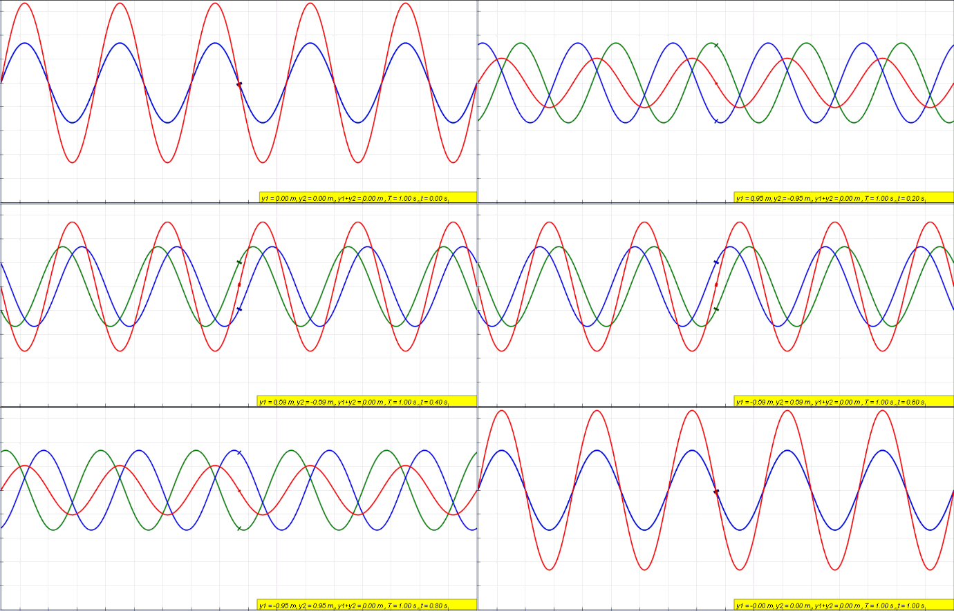
What if there is a mismatch in ZS and ZL impedances ? as load impedance increases, more power is dissipated in the load than in the source impedance, and so efficiency is increased. The magnitude of overall power is decreased, however, due to the increased resistance. Similarly, if the load impedance is decreased, a lower percentage of total input power is dissipated in the load, and efficiency decreases. In most RF designs, maximum power transfer is the primary concern. The mismatch will result in formation of standing waves in transmission line which causes variation in voltages within transmission line. Our intention here is to indicate the level of reflected wave in a moving coil meter.
 |
| Foward Wave, Reflected Wave and Standing Wave |
Directional couplers are passive devices used in RF networks. They couple a defined amount of the power in a transmission line to which can be used in another circuit. We will be building such directional coupler in a copper clad from which we will be taking output rectified voltage which will be indicated in moving coil meter. The instrument can be used in HF frequencies as well once properly calibrated.
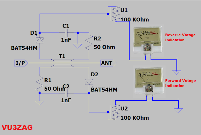
As our application of instrument is in VHF network we need to use fast switching diodes to get expected results. The directional coupler is etched on a double sided copper clad of 10cm X 6cm with 1.5 mm thickness . The Values of R1 and R2 are 50 Ohms (I have paralleled two 100 Ohm resistors), The Diodes D1 and D2 are Schottky diodes with better switching speed, I have used BAT 54. C1 and C2 are ac bypass capacitors of value 1nF. R3 and R4 are current limiting resistors which I used was 47KOhms. Later I removed the 47K resistors and connected a 100K Ohm dual variable pot so that I can set both the moving coil meters at a time during calibration. You can readjust it as per your moving coil meter parameters. I/P side is connected to Radio and ANT point is connected to antenna or test equipment. the moving coil meter I used is from a volt meter after removing series resistance.
 |
| SWR meter Circuit Diagram |
Calibration Steps
To calibrate we need to connect the Radio on input port of SWR meter and connect a dummy load of 50 Ohms (You can use 20, 1K 1Watt resistors in Shunt to make a 50 Ohm dummy load) on antenna port of the SWR meter. Tune the desired frequency and set the radio output power to 5 watt and press the PTT to send the carrier. Note down the forward and reflected voltage indication values. Set the pot U1 and U2 accordingly so that forward voltage full deflection is within meter display range. I have used a dual variable pot of 100k which will adjust both meter current simultaneously. The reflected voltage should be null as we are using resistive impedance which will math the source impedance of Radio.
SWR measurement
Remove the dummy load and connect with the actual antenna of which you want to measure the SWR. Note down the forward and reverse voltages. From the rate of deflection of reverse voltage meter we can get a rough estimation of whether the reflection is high or low. When reflected voltage is null or very close to 0 as compared to large deflection in forward voltage we can say that VSWR is very low. But if the reflected voltage is showing very high as compared to forward voltage we get an indication that VSWR is very high. If required we can fine tune the instrument and design a scale in the moving coil. Due to limitation in time and my purpose was achieved I just stopped here.
Here are some photo's of my prototype.


No comments:
Post a Comment